
Arriving at phenoptix towers this morning we noticed that a someone had searched the site for the trinket pinout. You might first ask what a Trinket is, well a Trinket(TM) is a teeny tiny ATTiny85 breakout from Adafruit and is available in two flavours 3.3V Logic and 5V Logic.

Despite its diminutive size the Trinket is a very useful bit of kit and has found a lot of uses in its short lifespan, thanks to the ease of use provided by Adafruit and their update to the Arduino IDE. You can also program it by our favourite program AVRDUDE! So I mentioned many uses, like what I hear you ask. Well like this:
(making a light ball thing)
(making a chip tune FM Transmitter - apparently with Rick Roll capabilities)
(driving NeoPixel strip! - now you're interested right?!)
So now you know what it is and what you can do with it, here's the good stuff. The Pinout (I would say Pin Out but I don't know what would be correct. Feel free to correct me in the comments.)

The diagram was provided by two cool folks in the Adafruit forums - ardunaut and the TheKitty. For a more technical view you might want to check out this schematic
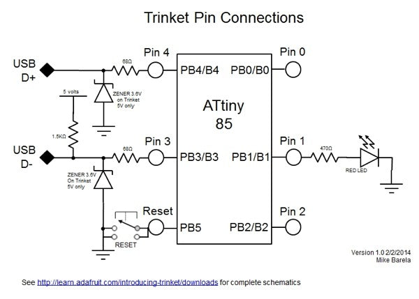
Frankly we're most interested in the GPIO pins right? Well on the Trinket Tutorial over on the Adafruit learning system Ladyada explains
All the GPIO pins can be used as digital inputs, digital outputs, for LEDs, buttons and switches etc. They can provide up to 20mA of current. Don't connect a motor or other high-power component directly to the pins! Instead, use a transistor to power the DC motor on/off
On a 3V Trinket, the GPIO are 3.3V output level, and should not be used with 5V inputs. On a 5V Trinket, the GPIO are 5V output level, and can be used with 3V inputs but may damage electronic devices that are 3V input only!
The first 3 pins are completely 'free' pins, they are not used by the USB connection so you never have to worry about the USB interface interfering with them when programming
- GPIO #0 - this is connected to PB0 on the ATtiny85. This pin can be used as a PWM output, and is also used for I2C data, and SPI data input.
- GPIO #1 - this is connected to PB1 on the ATtiny85. This pin can be used as a PWM output, and is also used for SPI data output. This pin is also connected to the onboard LED (like pin 13 on a regular Arduino).
- GPIO #2 - this is connected to PB2 on the ATtiny85. This pin can be used as an analog input (known as Analog A1), and is also used for I2C clock and SPI clock.
The next 2 pins are also used for USB programming. That means that when the Trinket is connected to a computer and in bootloader mode or in the middle of uploading a new program, they are used for sending data to/from the computer! It's possible to share these pins if you are careful. The best use of these pins is as outputs to things like LEDs , or inputs to things like buttons and just make sure not to press the buttons while connected to USB. We didn't want to keep these pins off the board but we strongly recommend not using them unless you're sure you need them since you might have to disconnect any connections to reprogram the Trinket!
- GPIO #3 - this is connected to PB3 on the Attiny85. This pin is used for USB programming, but its also an analog input known asAnalog A3
- GPIO #4 - this is connected to PB4 on the Attiny85. this pin is used for USB programming, but it can also be used as a PWM analog output and an analog input known as Analog A2
The rest of the details are equally well explained so check it out on their fantastic learning system.
You should now be able to find the Trinket Pinout and see what a great little product the Trinket is. Even if you're not into off the shelf electronics you can build one yourself, very cheaply! It might not be quite so handsome though!
Want to buy one right now? Click here!